Abstract
The field of wireless power transfer has gained immense popularity in the past few years with a lot of new products being launched by various companies for charging electronic devices wirelessly. But most of these devices use the principle of electromagnetic induction for power transfer and thus have a very short range. Here in this project we try to explore a relatively unexplored method for achieving wireless power transfer i.e. Ultrasonic waves. In this little experiment of ours we test the potential of ultrasonic waves as a means for wireless energy transfer. For this we used piezoelectric transducers (40 kHz)to convert ultrasound into electrical energy, this electrical energy was then fed storage circuit which extracts energy from the ultrasonic waves over a large period of time and then discharges in 5 seconds to give us an almost 5V constant DC supply.
Circuit Diagram and Explaination
Part 1:
The first stage of our circuit is a two stage voltage multiplier(peak to peak responding circuit) which converted the incoming sinusoidal wave into a (almost) DC signal
The first stage of our circuit is a two stage voltage multiplier(peak to peak responding circuit) which converted the incoming sinusoidal wave into a (almost) DC signal
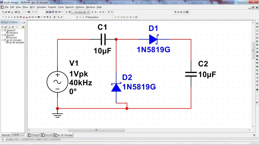
The diodes used for this circuit were 1n5819 which is a 0.3v schottky diode ,schottky diodes were used because of their lower voltage drop and better high frequency response. The value of capacitors were chosen by trying out different values and we got a higher voltage output within 1 second with least loading when connected to the second part of the circuit.
Part 2:
Part 2:
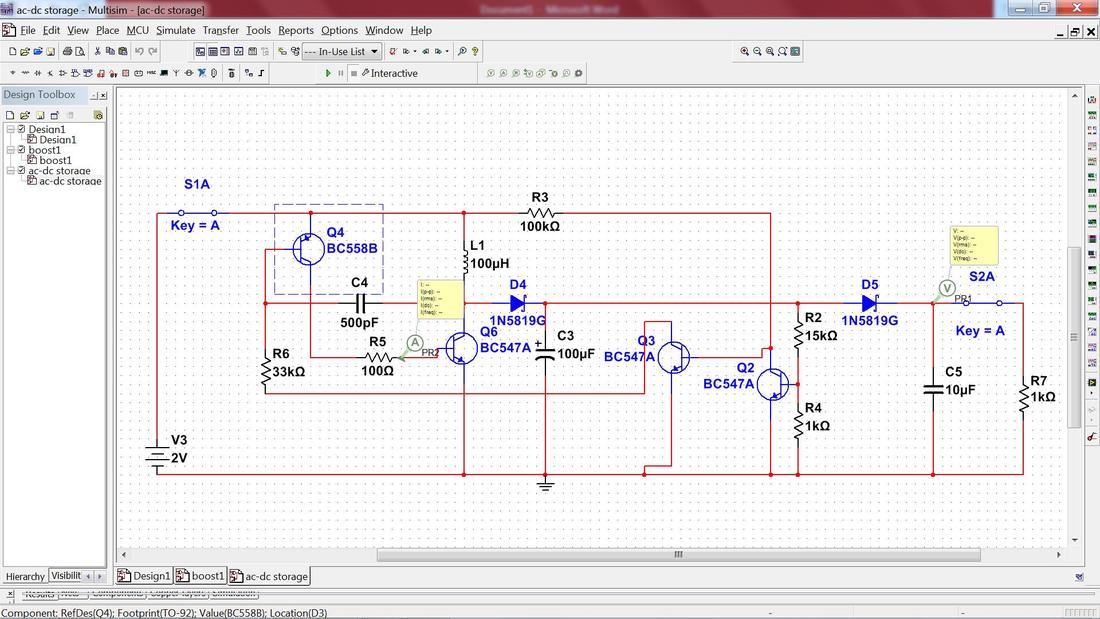
The second part of our circuit was a boost convertor which uses a two stage garners oscillator for generating the pulse to control the internal switch. This circuit stored energy from a low voltage dc source and converted it to a high volt dc this dc voltage was then used to charge a capacitor (c5) over a period of time(different for different distances) with the switch (S2A ) being open ,when the voltage of the capacitor reached a certain threshold the switch (S2A) was closed resulting to C5 being discharged across the load (denoted by R7) and then the switch was opened again after 5s and again the capacitor starts charging .
(Note :this opening and closing of S2A is supposed to be automatic but we didn’t do that in this implementation )
(Note :this opening and closing of S2A is supposed to be automatic but we didn’t do that in this implementation )
Eagle Files : Schematic and Board Layout
Stage I - Schematic
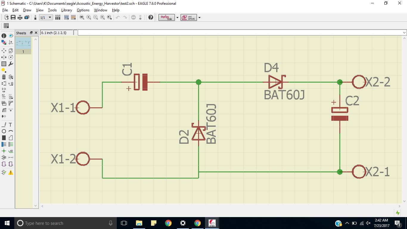
Stage I - Board File

Stage II - Schematic File
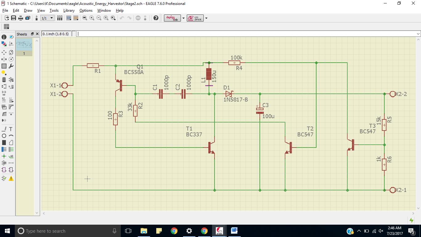
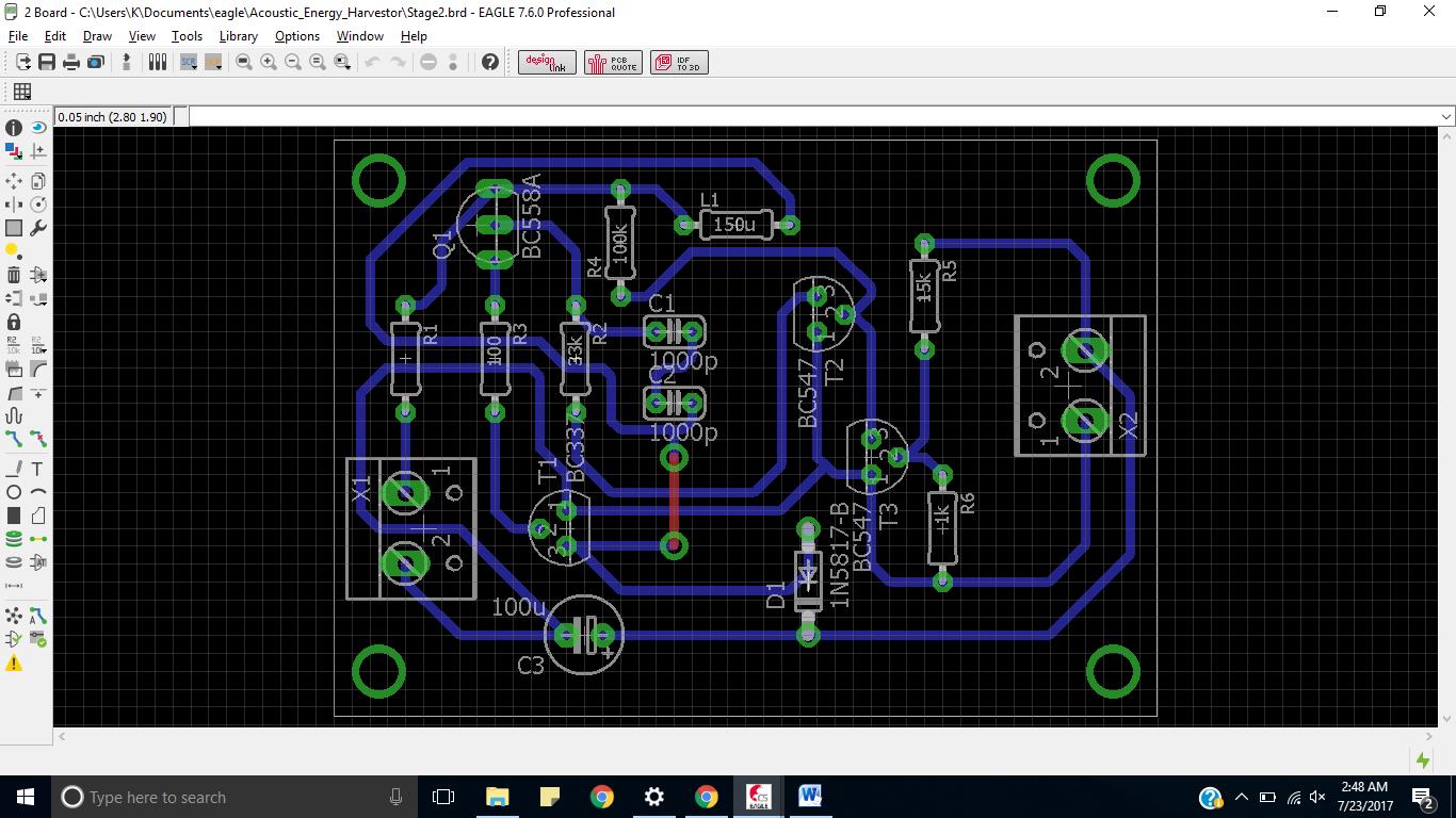
Stage II - Board Layout
The project was presented in TechEvince 4.0 - the annual Technical Exhibition of IIT Guwahati . Following are some pictures from the project display at the event
